dFab Lab
Technological Tools for a Changing Profession
Jump To...
Carnegie Mellon Architecture's Design Fabrication (dFAB) Lab equips young professionals with the skills to thrive in an increasingly fluid and technologically sophisticated model of practice. The lab is well positioned in a school of architecture with a strong legacy of innovation in design education and at a university renowned for the advancement and application of technology.
Note: To submit a 3D Printer job, please review and complete the form. Submissions are completed on a first come, first served basis. Last minute requests will not be permitted.
Contact: SoAdFAB@cmu.edu
Equipment
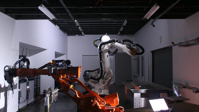
The Design Fabrication Lab (dFAB Lab) includes a range of professional level digital fabrication equipment to support student coursework and faculty research. These tools range from laser cutters to industrial robots and provide unique hands-on opportunities for students to explore the transformative potential of digital fabrication techniques upon the design and production of architecture.
-
Policy and Procedure
ABB IRB-4400 & IRB-6640: Robotic Cell
a. CLEAN UP: All mess, debris, scrap, stock, tools, material, must be cleaned and returned to original state
b. ROOM ACCESS: All entry into room must remain closed and locked except when necessary for project execution or preparation
c. TOOLS: All hand tools tagged with Blue Spray Paint & hosted in RobLab, never leave the room
d. DESKS: White Tables are for Computer/Clean Work ONLY
e. STORAGE: Project/Material Storage must be labeled. (3) day Storage Limit unless otherwise discussed
f. DOCUMENTATION: All Robotic research should be documented and stored within the dFAB Server (dFABSERVER1/DropBox – Robotics)
g. APPOINTMENTS: Equipment Reservations allow for Preparation, Testing, Research, Computer-Use, Operation and Robotic Related Work-Flows. Users must be mindful of limited time and shared space issues
h. OPERATION: Should the Operation require, all other Users must retreat to a safe work-zone and/or leave the space if deemed necessary by Operational Status. All Users yield to Reservation/Appointment Owner
ABB IRB-4400 & IRB-6640: Work-Zones
a. ALL WORK-ZONES: Work-Zones are provided for various Robotic Work-Flows. With advance notification and permission, Users may alter position and affix custom jigs, tools or objects to ROBLab mounting Surfaces. Users are expected to breakdown, clean, and return Work-Zones to their original state. Altered Work-Zones are subject to change and movement throughout the semester
b. 3D ENVIRONMENT: Users are responsible for ensuring proper development and setup of 3D Environmental requirements for successful RAPID Code Generation/Simulation
c. ROLLING VACUUM TABLE: Rolling Vacuum Table is for Robotic Work-Flows ONLY. Vacuum Table utilization must be discussed in advance, prior to Reservation/Appointment. With approval, Past and/or Current Projects, Set-Ups, Jigs, etc. will be removed for Reserved User Appointments
d. STEEL TABLE: Steel Table is for Robotic Work-Flows ONLY. Steel Table utilization must be discussed in advance, prior to Reservation/Appointment. With approval, Past and/or Current Projects, Set-Ups, Jigs, etc. will be removed for Reserved User Appointments
e. WALL-MOUNTS: Wall-Mount Jigs are for Robotic Work-Flows ONLY. Wall Mount Jig utilization must be discussed in advance, prior to Reservation/Appointment. With approval, Past and/or Current Projects, Set-Ups, Jigs, etc. will be removed for Reserved User Appointments
f. ROTARY TABLE: Rotary Vacuum Table is for Robotic Work-Flows ONLY. Rotary Vacuum Table utilization must be discussed in advance, prior to Reservation/Appointment. With approval, Past and/or Current Projects, Set-Ups, Jigs, etc. will be removed for Reserved User Appointments
g. DESKS: White Desks are for Computer/Clean Work ONLY
h. WORK-TABLE: Work Tables are positioned throughout the lab for Fabrication related work-flow. Work-Table usage must be approved beforehand. Users must label their work and clean-up afterward
ABB IRB-4400 & IRB-6640 : Manipulators, External Devices, Controllers & TeachPendants
a. DO NOT:
- Push ANY buttons on the robot
- Unplug ANY connections on the robot or ATI Robot-Side interface
- Climb or physically engage robot
- Place non-toolside objects on the robot
- Store/place objects on the Track
b. CONTROLLERS:
- should remain ON
- Cases will not be opened by User
c. TOOL PLATES:
- All ATI tool plates are to be dismounted and returned to default configuration (user custom tools removed).
d. TEACH PENDANT (TP):
- TP is to be treated with GREAT CARE. User is subject to Fines and/or Fees related to TP misuse
- TP menu user access is restricted to the following:
- HotEdit, I/O’s, Jogging, Program Editor, Program Data, Production Window
- User Modules should be uploaded to the USER MODULES folder
System Modules and other core files are not to be altered nor delete
ABB IRB-4400 & IRB-6640 : Operation
a. UNIVERSAL:
- All Operations will be simulated prior to execution
- All Users will be aware of non-simulated variables, dress pack, work surface etc.
- Space will be cleared of debris and extraneous material, taking into account all moving parts of the manipulator not just the TCP
- Operator will be sober, awake and attentive at all times of operation
- Operator may be accompanied by other users, teammates, and robotic authorized personnel
- Robot will not physically engage living organisms.
b. MANUAL MODE:
- Users will remain clear of working perimeter
- Operator may be accompanied by other Users and Robotic Authorized Personnel.
- Operator will hold TP properly while motors on
- Users should not interfere with environment while motors on
c. AUTO MODE:
- All Non-Essential Personnel are to leave the area
- All Essential Personnel are to be on the SAFE side of the light curtain with required Safety Equipment
- Speed will not be permitted to exceed 2000mm/s at all times for any operation
d. TOOLING: When using Dangerous Tooling Attachments (i.e. Spindle, WireSaw, Plasma, etc.)
- All Non-Essential Personnel are to leave the room entirely
- All Essential Personnel are to be on the SAFE side of the light curtain with Safety Equipment
- Operator will be accompanied by at least one authorized user
- Stock is to be properly secured
- Work with particular tools will only occur in designated work zones
e. TOOLING: When using Less Dangerous Tooling Attachments (i.e. Gripper, Hot-Wire, Sensory Apparatus etc.)
- Follow Protocol for Mode of Operation
f. SPECIAL CASES: Live Command, Indeterminate Operation
- Modules that may produce Non-Simulative Motion Variability are to only be executed under direct supervision by Admin or Advanced User. Auto-Mode rules apply. Active tooling with indeterminate operation should be executed with extreme caution and supervision, and should be preceded with rigorous testing and simulation.
-
Procedure
- PREPARATION: Users must sufficiently prepare a 3D model using software of their choosing. dFAB personnel will provide minimal troubleshooting assistance. dFAB Personnel will not provide in-depth instruction or training with 3D modeling software outside of courses. Make certain that your 3D model meets the minimum wall thickness requirements as indicated in Policy C.
- EXPORT: 3D-Models should be exported as a Stereo-lithography file type [STL] in millimeter [mm] units. If the file includes multiple parts, each part should be exported separately as its own file.
- CHECK: Open your STL file in Rhinoceros 3D. Type ’MESH REPAIR’ into the command prompt and press ENTER. A new window will appear indicating all problem areas (if any). If the window indicates ‘This is a Good Mesh’ then proceed to Step 5.
- TROUBLESHOOTING: If your file reads as a ‘Bad Mesh’, then it is not capable of 3D printing, and requires troubleshooting. Visit the dFAB website, and browse available 3D printing tutorials for assistance.
- SUBMISSION: Click 3D Printer Submission Form link and closely follow instructions to submit file.
- REVIEW: dFAB staff will review your file and confirm whether it will print on the desired machine. If rejected by the machine’s software, the user will need to make the necessary changes to the STL file and resubmit.
- PICK UP: You will receive an email when your part is ready for pick up or if there are any additional issues with your file during the print process.
3D Printers
Ultimaker S3 Printer
Maximum Build Size: 8.6in. x 7.1in. x 7.5in.
Filament Thickness: 2.85mm
Layer Resolution: 0.06 -0.3mm
Minimum Wall Thickness: 1mm
Print Color: Various (See dFAB Lab Staff)
User Pricing: See dFAB Lab Staff
Image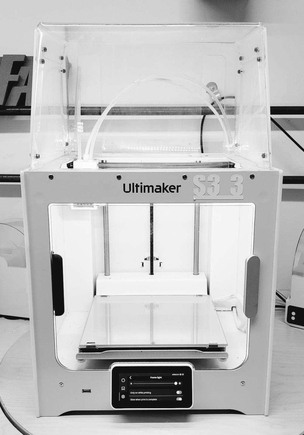
Ultimaker S5 Printer
Maximum Build Size: 12.6in. x 9.1in. x 11.4in.
Filament Thickness: 2.85mm
Layer Resolution: 0.06 -0.3mm
Minimum Wall Thickness: 1mm
Print Color: Various (See dFAB Lab Staff)
User Pricing: See dFAB Lab Staff
Image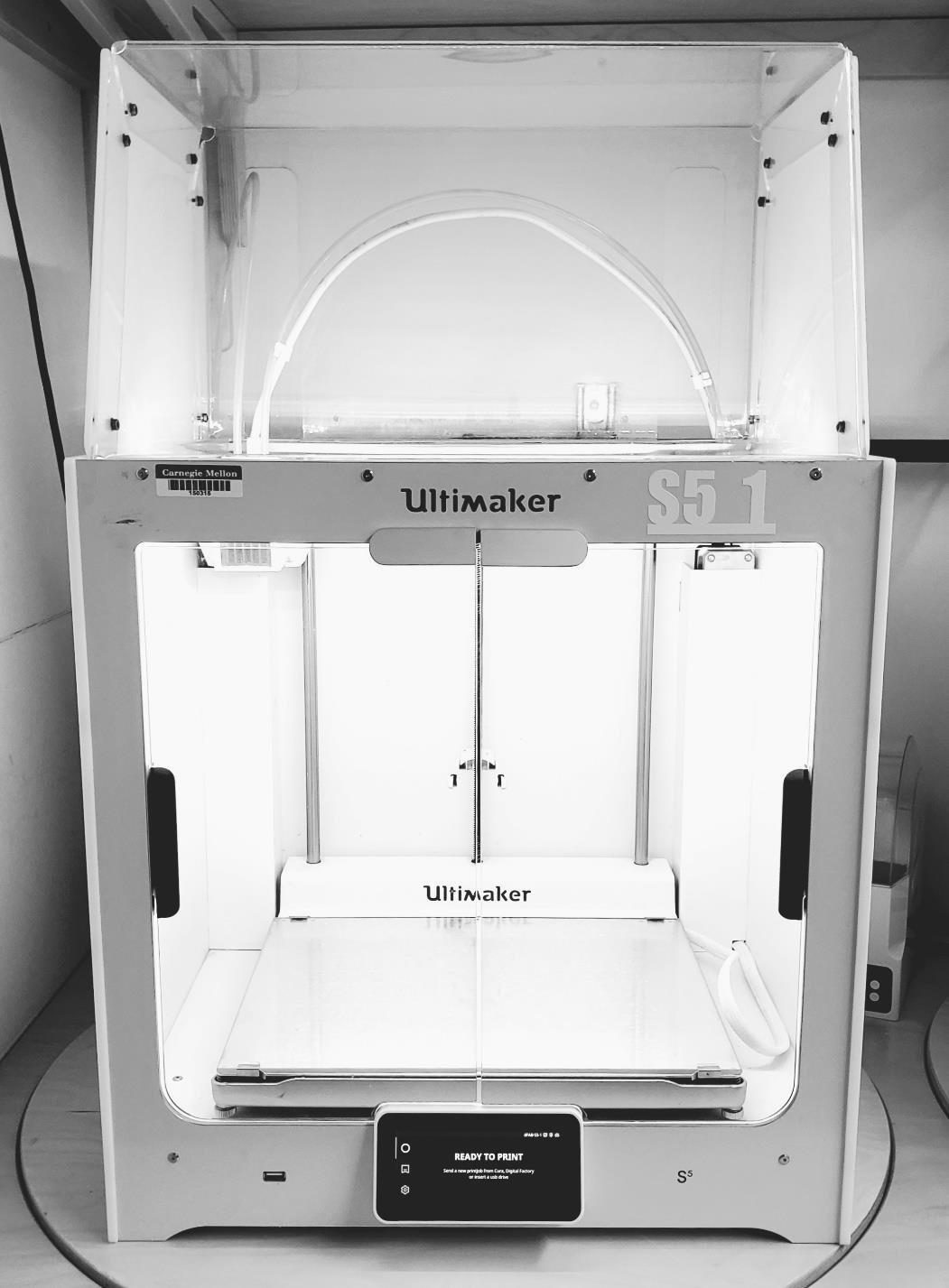
Bambulab Printer
Maximum Build Size: 9.5in. x 9.5in. x 9.5in.
Filament Thickness: 1.75mm
Layer Resolution: 0.08 -0.28mm
Minimum Wall Thickness: 1mm
Print Color: Various (See dFAB Lab Staff)
User Pricing: See dFAB Lab Staff
Image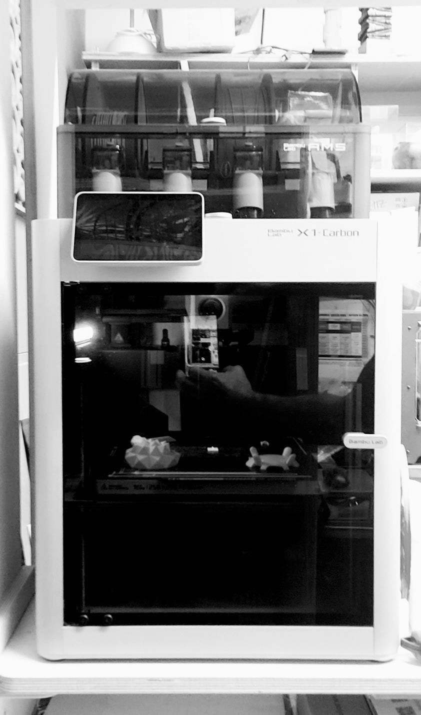
Projet 360 Powder Printer
Maximum Build Size: 10in x 8in x 8in
Layer Resolution: .004in
Minimum Wall Thickness: .125in
Minimum Column Diameter: .250in
Print Color: white
User Pricing: $0.09/cu.cm. (Powder)+$0.25/mL(Binder)+$4.00 Printhead fee
Image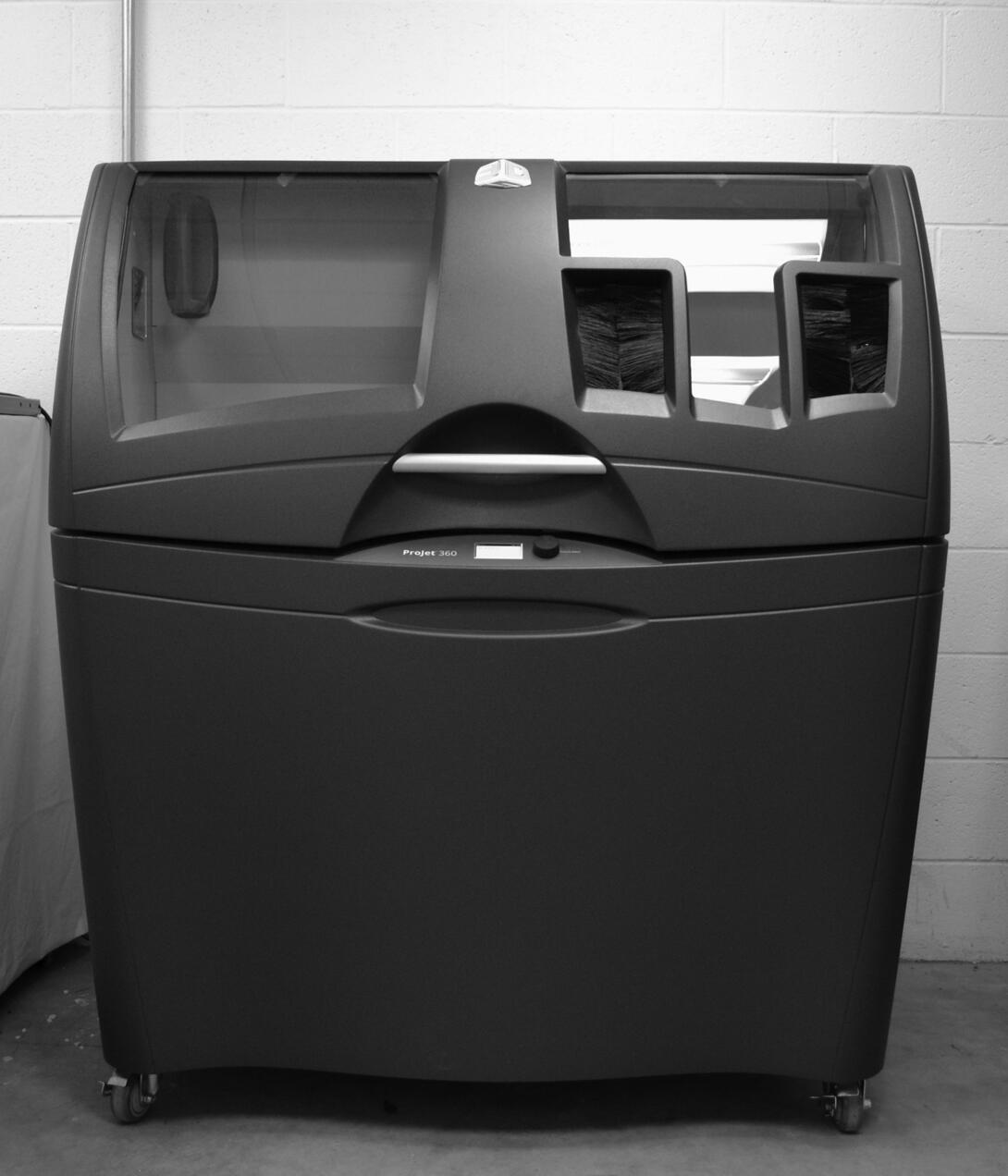
-
Procedure
- RESERVATIONS: Students must show dFAB Staff a ready Rhinocam file to get reservation time on the machine. dFAB Staff will place and cancel all CNC Router machine time reservations.
- CHECK IN: Before your Reservation begins, you must Check-In with a dFAB Staff Member. Surrender your Andrew ID Card, and retrieve an Equipment Tool Kit. After which, you may utilize the Equipment.
- PREPARATION: NC Files should be sufficiently Prepared within (15) Minutes of your Reservation Start Time.
- FINAL APPROVAL: Your File should be Re-reviewed and Simulated by dFAB Staff before Equipment Utilization.
- POST: File must be Posted to the CNC Router Temp folder, on the dFAB Server- in a Folder with your Andrew ID as the Title. (dFAB DropBox – CNC Router/ Program/ Year/ AndrewID/ Post) dFAB Staff must edit the Code in your Post if your Material/Stock is less than or equal to 4′ Length by 4′ Width.
- FASTENING: Set your Material on the CNC Work Table, and ensure the Material will hold properly by turning on the Vacuum Table via WinCNC Application Interface. For Material Larger than 4′ Length by 4′ Width, find and select the ‘VAC FULL’ Button within the WinCNC Interface. For Material smaller than or equal to 4′ Length by 4′ Width, find and select the ‘VAC FRONT’ Button within the WinCNC Interface. (VAC FULL = 8′X4′ Table Vacuum; VAC FRONT = 4′x4′ Front Table Vacuum) If your material does not hold, you may use Double-Sided Tape (provided in your Equipment Tool Kit), or brace your material with other scrap material pieces. Bracing Material must be less than or equal in Thickness; and less dense. (i.e. Foam is less Dense than Plywood) NOTE: Screwing your Material to the CNC Work Table is not approved!
- PREVIEW: Preview your File within the WinCNC Interface by opening your Post File, then find and select the ‘Preview’ Button. Your Toolpaths will appear in the Preview Pane on the WinCNC Interface. Make certain that your Toolpaths are properly aligned with the Origin Point.
- SIMULATE: Simulate your Post within the WinCNC Interface by loading your Post File, (this should be open already, see previous step) then find and select the ‘Simulate’ Button. A new window will appear with an Estimated Time of Completion in the lower Right-Hand Corner of the Window. PLEASE NOTE: You are limited to your Appointment Time! dFAB Staff will not approve extended Equipment Time for File Completion. Your Appointment will end (15) Minutes prior to the End Time, to allow for sufficient Clean-Up.
- DUST COLLECTOR: Turn the Dust Collector ‘ON’ BEFORE your File Begins. This is a Manually Activated Button located on the Wall of the CNC Room. Green = ‘ON’; Red = ‘OFF’.
- SAFETY: If you are in the CNC Room; you are REQUIRED to wear Protective Eye-Wear while the CNC Router is in Motion. These are available in your Equipment Tool Kit. Additional Safety Gear is also provided, but considered Optional: Breathing Mask & Ear Protection.
- GO: After all previous tasks are completed; Find and Select the ‘Start’ Button within the WinCNC Interface. Alternately, you may Press the ‘ENTER’ Key, twice- to begin your CNC File.
- PAUSE: Find and Select the large, gray, ‘PAUSE’ Button, within the WinCNC Interface. The CNC Equipment will Pause, but the Spindle and Vacuum Table will continue to Run. You may approach the Equipment, and perform various tasks- as long as you: are wearing Protective Eye-Wear, all loose clothing (scarves, long-sleeves) and hair is restrained, remain aware of moving parts.
- STOP: Find and Select the large, red, ‘ABORT’ Button, within the WinCNC Interface. The CNC Equipment will retract to a safe ‘Z’ Clearance Height, and remain stationary on the ‘X’ and ‘Y’. The Spindle will REMAIN ON! To continue safely utilizing Equipment, you must turn the Spindle ‘OFF’ by finding and selecting the small, gray ‘SPINDLE’ Button, within the WinCNC Interface.
EMERGENCY: Immediately remove yourself from danger.
a. DO NOT remain or return to the room unless it is SAFE to do so. Please allow the Equipment to continue its process. Collisions, Material Interference, and Tool Breakage are all possible outcomes. However, your safety is of immediate and prominent concern. Allow the Equipment ‘run its course’, if necessary.
b. IF THE AREA IS SAFE, find and depress the red, ‘E-STOP’ Button, located on the FRONT, TOP, RIGHT-HAND Corner of the Blue Controller Box. Contact a dFAB Employee immediately. Alternately, you can find and PULL the pink/orange E-STOP Cord, running around the entire machine. This is a less preferred method, due to the proximity of the User and the Equipment.
- CLEAN: You must stop any existing processes on the CNC Equipment within (15) Minutes of your Equipment Reservation End Time. After ALL Processes have terminated, you must return the Equipment and the Area back to its original state. Scrap Materials must be taken to the Dumpster, located behind MMCH. (Trashcans are available upon request, must be emptied before they are returned) Brooms, Dust Collector Hoses, and Air-Tools are all provided and located within the CNC Room for your dust & debris cleaning needs. Users are REQUIRED to wear Breathing Masks while cleaning the CNC Room. dFAB Staff is NOT Required to assist ANY Student User with Clean-Up or Large Scrap Removal. Please plan accordingly.
- CHECK OUT: Return the Equipment Tool Kit with all items in tact and accounted for. After dFAB Staff reviews and approves Equipment and Area Sufficiency, your Andrew ID Card will be returned to your possession.
Overview
Specifications:
Workzone Size: <= 8′x4′Maximum Material Thickness: 5″Available Milling Tool Diameter: .25″; .375″; .5″; .75″ (Carbide & High-Speed Steel)Available for Purchase Milling Tool Diameter: .0625″; .125″; Various Compression Spiral Tools (Carbide)Available Drilling Tool Diameter: 3mm; 5mm; 6mm; 8mm (Carbide)Miscellaneous Milling Tools: Engraving, Compression, Lollipop
Available Application Environments: RhinoCAM, MasterCAM, WinCNC, Rhinoceros, Illustrator
Important Notes:
- Approved Materials: Plastics, Lumber, Foam
- Disallowed Materials: Homasote, Drywall, Steel (Ferrous Metals)
- See Manager Regarding Milling Operations involving: Aluminum, Plastics
- The CNC Equipment is for Research & Learning Purposes ONLY. Crafts, Gifts, ‘Buggies’, and Carnival Projects are disallowed on this Equipment.
- Files MUST be prepared before creating Equipment Reservations.
- Dust Collection Systems must be turned ‘ON’. Protective Eyewear is REQUIRED. Dust Masks and Ear Protection are provided and highly recommended. Closed-Toe Shoes are also recommended.
- Fire is a primary concern when utilizing this Equipment; as a result, you are REQUIRED to stay within the CNC Room/Area while your Job is running. If a Fire should occur, STOP the Job, and notify dFAB Staff immediately.
-
Procedure
- CHECK IN: Before your Reservation begins, you must Check-In with a dFAB Staff Member. Surrender your Andrew ID Card, and retrieve an Equipment Tool Kit. After which, you may utilize the Equipment. To turn on the Computer Monitors, you must find the Remote Button, located in your Equipment Tool Kit.
- PREPARATION: Files should be sufficiently Prepared, and Materials must be Purchased and Cut-to-Size within (15) Minutes of your Reservation Start Time.
- MATERIAL: Place your Material inside of the Laser Equipment. Avoid interference and collisions with fragile Equipment Parts such as the Laser Lens Assembly, and the Honeycomb Laser Table. Make certain that your Material is not: sufficiently warped, larger than 3/8″ in thickness, an unapproved Material, cut-to-size. If your material is warped, you may use MASKING TAPE ONLY, to correct the insufficiency. If Masking Tape does not work- then you may not use the Material.
- POST: Prepare your settings within the Epilog Print Driver, try to use the recommended settings for your Material and Process needs. Make sure that the ‘Auto Focus’ Option is Selected.
- PRINT: Send your File to the Laser Equipment. From the Laser Equipment Interface, find and select the green ‘GO’ Button. Your File will begin.
- PAUSE: Find the red ‘STOP’ Button located on the Equipment Interface, and press it ONCE. Your file will continue cutting until it reaches an ‘endpoint’ in its defining line geometry; then the Laser Lens Assembly will freeze, and stop firing the laser. You may safely open the Laser Equipment lid. You may not remove and/or move your material. Close the Lid, then Find and select the green ‘GO’ Button on the Laser Equipment Interface to continue your Laser Job.
- STOP: Find and Select the red ‘STOP’ Button on the Laser Equipment Interface. Your file will continue cutting until it reaches an ‘endpoint’ in its defining line geometry; then the Laser Lens Assembly will freeze, and stop firing the laser. Find and Select the red ‘RESET’ Button on the Laser Equipment Interface, and the Laser will return to its Origin. After which, you can open the Equipment Lid, Move/Remove your material, or send another job.
- EMERGENCY: Find and Depress the EMERGENCY STOP Button located on the FRONT, RIGHT-HAND Side of the Laser Equipment. Contact a dFAB Employee immediately.
- CLEAN: Within the final (5) Minutes of your Equipment Reservation, you must terminate all Equipment Processes and begin cleaning. Use a Vacuum to clean the Honeycomb Laser Table, while avoiding strong collisions with the table or Laser Lens Assembly. Remove all scrap and debris- place in available Trashcans. DO NOT overfill the Trashcans, notify a dFAB Employee, and a new trashcan will be provided.
- CHECK OUT: Turn OFF the Computer Monitor with the Remote Button located in your Equipment Tool Kit. Return the Equipment Tool Kit with all items in tact and accounted for. After dFAB Staff reviews and approves Equipment and Area Sufficiency, your Andrew ID Card will be returned to your possession.
-
Procedure
- CHECK IN: Before your reservation begins, you must check-in with a dFAB staff member. Only after first checking in may you utilize the equipment.
- PREPARATION: Molds must be completely dry and free of all particulates. Materials must be purchased and cut-to-size within fifteen (15) minutes of your reservation start time.
- START UP: Turn the equipment "on" by pulling down on the circuit switch on the rear wall of the vacuum forming area.
- WARM UP: Using the turn-dial knobs on the vacuum former, adjust to the desired heat settings and locations. Each knob controls a different heating element area, and some may be unnecessary depending on the size of your vacuum forming window. Also, too much heat can cause your material to boil/bubble. Heating up slowly and at lower temperatures is highly recommended.
- WINDOW: Install necessary window size for your specific workflow. The re-sizing windows are easily removed/installed with hand tightened/loosened nuts and bolts. The vacuum former includes two window sizes: 24″ x 24″ (vac form material must be cut-to-size at 26″ x 26″ minimum); and 11″ x 11″ (vac form material must be cut-to-size at 12″ x 12″ minimum). Alternately, you can opt to use the equipment without re-sizing windows, and utilize the full bed: 25″ x 25″ (vac form material must be cut-to-size at 27″ x 27″ minimum).
- PLACEMENT: Pull forward on the vacuum former arm on the right side of the equipment. This will raise the bed within the vacuum chamber. Place your mold within the vacuum forming window and ensure 3/8″ to 1/2″ of clearance from the edges. Make sure the steel screen mesh is sitting underneath the mold. Lower the bed slowly by pushing the vacuum former arm backward. Unlock the window frame and "sandwich" your thermo-plastic material within the re-sizing windows. Lock the window frame with your thermo-plastic properly aligned and placed. Pull the heating element frame over top of your framing window.
- STATES: Your material will go through three (3) states of change. First, the material will deform unevenly and warp upward. Second, the material will begin to level off completely and become very glossy. Lastly, the material will begin to sag downward into the vacuum chamber. During the final stage, your material will become very "sheet-like" and malleable. If you bump the machine lightly with your hand you will see the material bounce somewhat. You can also push the heating elements back and lightly touch or press on your material. Make sure the edges are malleable enough to pull down and around your mold.
- VACUUM: When your material reaches a sufficiently malleable state, casually push the heating elements backward to terminate the heating process. Pull the vacuum former arm forward to raise your mold and plastic material up through the window. Find and flip the rocker switch labeled "pump" on the equipment to turn the vacuum "on" and pull your plastic down into/onto your mold. If you notice limited change, use your body weight to push down on the window frame handles in the front of the machine to assist with the vacuum’s pull and ensure a complete seal in the vacuum chamber.
- COOL: When your plastic reaches a point where it can be handled safely, turn the pump "off." Alternately, you can reverse the air-flow in the vacuum chamber by finding the toggle labeled "pressure" and pushing it downward. This will assist with de-molding your plastic from the mold. Please note that the pressure toggle should be pressed completely downward or left in its normal position; there is no "in-between" state.
- REMOVE: Unlock and lift the framing window and remove your part.
- SHUT DOWN: Clean and remove any debris or scrap left in/on the equipment/area. Turn all heating knobs back to the "off" position. Turn the equipment "off" by returning the circuit switch back to its upward position. Leave re-sizing windows as they are.
- EMERGENCY: Return the heating elements back to their home position. Contact a dFAB employee immediately.
Equipment Specifications
Window Sizes: 11″ x 11″; 24″ x 24″; 26″ x 26″
Maximum Depth: 14″
Sheet Sizing: 12″ x 12″; 25″ x 25″; 27″ x 27"
Sheet Thickness: <0.25″Important Notes
- The vacuum forming equipment is for academic research and coursework ONLY. "Buggy" parts and fabrication are not permitted on this equipment.
- Ensure that all sealed and/or laminated molds are dry before vacuum forming, such as clear coats, shellac, wood glue, latex paints, etc.
- CHECK IN: Before your reservation begins, you must check-in with a dFAB staff member. Only after first checking in may you utilize the equipment.
Software
The Design Fabrication Lab's (dFAB Lab) facilities include multiple digitally-controlled equipment platforms. Each process and procedure is carried out by a digital workflow coordinated by the operator. The digital workflow consists of several items, but primarily utilizes software and application environments in which the operator develops, edits, and processes 2D and 3D geometry. These digital environments are sorted into three (3) tier groups:
- Primary: Primary applications are typically CAD (computer aided drafting/design) environments. Users begin their workflow from this tier by developing 2D and/or 3D geometry that will eventually be utilized for a secondary environment.
- Secondary: Secondary applications usually take the primary application geometry, and provide an interface in which the user might adjust/edit settings affiliated with the method in which the chosen equipment processes the geometry.
- Bridge: Bridge applications communicate the information developed from the secondary application to the equipment. Users are trained on every detail of the digital workflow, including material/tool selection, and the software/application environments. A list of available dFAB software/application environments, organized by tier, is listed below.
Tier 1 – Primary Environments
- Rhinoceros 3D
- Grasshopper
Tier 2 – Secondary Environments
- 3D Systems 3DPrint
- Ultimaker Cura
- Bambu Lab Bambu Studio
- RhinoCAM
- MasterCAM
- Epilog Dashboard
- RobotMaster
- ABB RobotStudio
Tier 3 – Bridge Environments
- WINCNC
- 3D Systems 3DPrint
- Ultimaker Cura
- Bambu Lab Bambu Studio
- ABB RobotStudio
Materials
Plastic
The lab stocks various plastics available for purchase. Acrylic is possibly the most commonly used and is often referred to as Plexi-glass. Acrylic comes in various tints and colors and is suitable for the laser cutter. P.E.T.G. and PolyStyrene are thin plastics used for vacuum forming.
Acrylic
Acrylic is either extruded or cast. While cast acrylic offers better machinability and laser cutting, extruded acrylic is typically more cost effective. Acrylic is typically laser cut to create a more professional finished model. dFAB stocks acrylic in clear, white, and black in 1/32 inch, 1/16 inch, 1/8 inch and 1/4 inch nominal thicknesses.
PETG
Poly Ethylene Terephlalate Glycol (PETG) is a transparent thermoplastic sheet. It is typically more impact resistant than acrylic, and also more cost effective. Its malleability offers deep draws for Vacuum Forming. dFAB stocks PETG in 1/32 inch and 1/16 inch nominal thicknesses.
Polystyrene
Polystyrene (PS) is economical, and is used for producing plastic model assembly kits, plastic cutlery, CD “jewel” cases, smoke detector housings, license plate frames, and many other objects where a fairly rigid, economical plastic is desired. Production methods include stamping and injection molding.This material is more commonly used for Vacuum Forming because of its malleability. dFAB stocks Polystyrene in 1/32 inch and 1/16 inch nominal thicknesses.
Wood
MDF / ULDF
Medium-density fiberboard (MDF) is an engineered wood product formed by breaking down hardwood or softwood residuals into wood fibers, often in a defibrator, combining it with wax and a resin binder, and forming panels by applying high temperature and pressure. MDF is commonly more dense than plywood. We typically stock Ultra-Light Density Fiberboard (ULDF) which allows for quicker, safer, and more efficient machining. For scale modeling and prototyping, this material works best because of its forgiving nature towards the bits. This material is easily machined, sanded and strong. dFAB stocks Ultra-Light Density Fiberboard in 1/2 inch and 3/4 inch nominal thicknesses.
Plywood
Plywood is made from laminations of veneer. It is light but strong and has many other good properties. Plywood is used to make longboards (skateboard), giving it a strong yet flexy ride. It is also used (often in very thin grades with many laminations) for making model aircraft. This wood product offers strength, with a light weight- but also maintains its beauty. Suitable for any woodworking project. dFAB stocks Birch, Revolution and AC Plywood in 1/4 inch, 1/2 inch and 3/4 inch nominal thicknesses.
Foam
XPS Foam
Extruded polystyrene foam (XPS) consists of closed cells, offers improved surface roughness and has higher stiffness and reduced thermal conductivity. Typically offered in pink, blue, or green, it has adopted the name ‘Pink Foam.' This material is typically used for milling because of its forgiving nature towards bits and equipment as well as its machinability. You cannot spray paint, or vacuum form these materials because they will melt. There are other more expensive options that allow for easy sanding, painting, resin coats, and vacuum forming such as Polyurethane Foam. The lab however, does not have this material readily available. dFAB stocks XPS foam in 2 inch nominal thickness.